warrick controls wiring diagram
The main wires should enter the upper left side hole below which are the grounding and bonding bar on the left. Wiring terminals for intrinsically safe circuits must be separated by at least 2 inches 50 mm from non-intrinsically safe termi-nals.

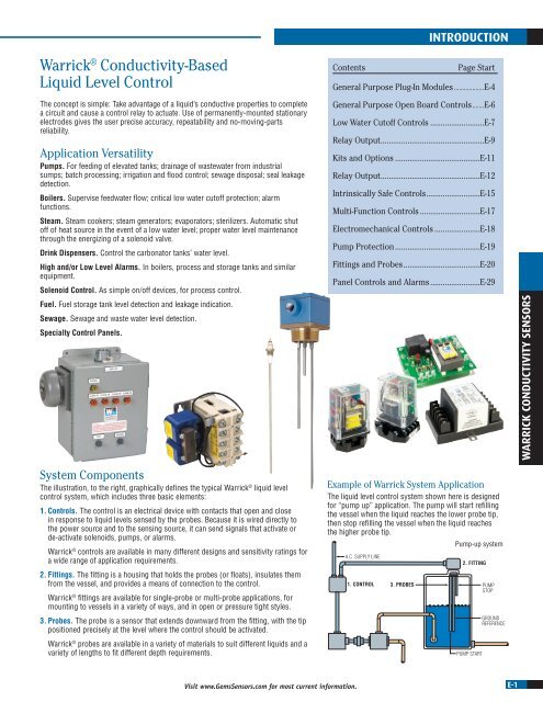
Warrick Conductivity Sensors Gems Sensors Pdf Catalogs Documentation Boating Brochures
Warrick Fittings Spare Parts.

. Series LWC700 Self-Contained Low Water CutOff and Water Make Up. Inside panels field wiring terminals for. Wiring terminals for intrinsically safe circuits must be separated by at least 2 inches 50 mm from non-intrinsically safe termi-nals.
Wire the control device s to the Series 27 relay as shown. Wire control per wiring diagram following NEC and local codes. Warrick Controls Wiring Diagram.
Mount the control or enclosure vertically on wall or other solid structure with the transformer on the left-hand side. Wire Series 2800 as indicated on drawing. Install control module in socket.
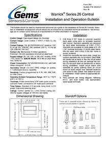
Loosen the cover screws and open the cover of the spa control. Read customer reviews find best sellers. Warrick Series 26M Control Installation and Operation Bulletin Specifications Control.
The control must be situated in a non-hazardous area where an explosive atmosphere will not exist at any time. And local codes 3. Search for jobs related to Warrick controls wiring diagram or hire on the worlds largest freelancing marketplace with 20m jobs.
Wire the control device s to the Series 27 relay as shown. Warrick 26 and DF Series Fault Code Troubleshooting. Wire control per wiring diagram following NEC.
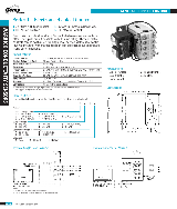
Internal Wiring Diagram 12 3 4 5 6 78 910 Dimension diagram of open control Contact Configuration 3 316 G is shown 1 516 3 316 1 516 2 12 4 14 3 keyholes for 6. Wire control per wiring diagram following NEC and local codes. SB1350 Self-Containled Conductivity Liquid Level Control.
Install control module in socket. Wiring terminals for intrinsically safe circuits must be separated by at least 2 inches 50 mm. Its free to sign up and bid on jobs.
Series LWC800 Self-Contained Low Water CutOff. Warrick Series 16M Controls Installation and Operation Bulletin Form 167. Download the Gems Sensors Controls ELS-1150 installation instructions bulletin.
Download the Gems Sensors Controls. For example if a module is powered up and it. Warrick Relays Troubleshooting Guide.
Gems Sensors Controls. Terminals on the control are. Warrick Controls Wiring Diagram To properly read a wiring diagram one offers to know how the particular components in the method operate.
Warrick controls wiring diagram Minggu 30 Oktober 2022 Edit. Intrinsically safe wiring must be kept separate. Gems Sensors Instructions 16VM Variable Resistor.
Download the Gems Sensors Controls ELS-1150 installation instructions bulletin. Series 26M Bench Test. Warrick 26 and DF Series Fault Code List.
With more than 12 million units sold since 1987 the Series 60 was the most widely used heavy-duty truck engine.
Warrick Boilerdata Com

Dfl1a0k040406 Warrick Dfl1a0k040406 Dual Function Relay Output Control 10k Ohm Inverse Operating 120v 1 16 Panel Mount Industrial Stores
1g1d0 Warrick Controls Industrial Trading
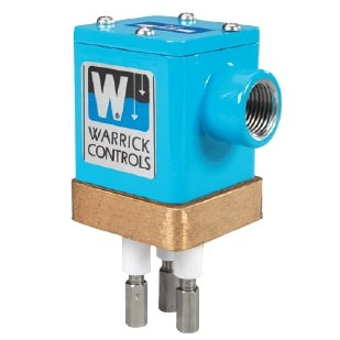
Warrick Conductivity Based Liquid Level Control Pressure Switch
Warrick 1g1d0 Lsll 6101 Pdf Docer Com Ar

Warrick Controls Gems Sensors Boiler Control Relay 16dma1a0 Ebay

Warrick 26nmc1b0 Relay Gsistore

1f1d0 Warrick Controls Industrial Trading

Warrick 26nmb1a0a Low Water Cut Off
Warrick Series 26 Control Installation And Operation Bulletin

Warrick Controls Liquid Level Control Relay 16vmp1a0 Solid State Ebay

Warrick Controls 16vmc1a0 120v Level Controller W Base Ebay

27a1e0 Warrick A Brand Of Gems Sensors Intrinsically Safe

Warrick Pdf Resistor Relay

Warrick 1g1d0 1no 2nc Pole Relay Controller 115v Ac 300v Ac B295585

Warrick 16vma1m0 Level Control Module Relay 120v Ac D347891

Warrick Controls 16md1m0